
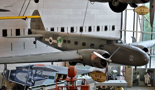
The Boeing 247 revolutionized civilian air travel through high speed, passenger comfort, and futuristic designs not seen by the previous airliners, virtually rendering them obsolete in a single day. Some examples of earlier airlines consisted of the Ford Tri-motor “Tin Goose,” the Fokker F-10 Super Trimotor, and the Curtiss Condor biplane. These airliners were usually underpowered for their size with open engines and large fixed landing gear resulting in a large drag coefficient and overall poor performance with long flight times between destinations.

Ford Trimotor 
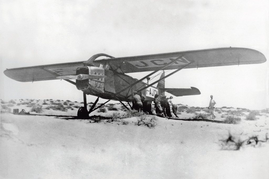
Fokker F-10 
Curtiss Condor
The first flight of the Boeing 247 happened on February 8, 1933, and enters into service with United Air Lines on March 30, 1933, launching United well above the competition. The Eastern division of United received the first delivery in April. By the end of September, the entire fleet is in service operating in all of the United Air Lines territories. The 247 sets the trend for future airlines with United on top and momentarily deems all other current airliners out-of-date for about a year until the Douglas DC-2 entered the market on May 11, 1934, for TWA.
United ordered sixty planes in 1932 after seeing a final version model with the first batch of fifteen airplanes entering production by mid-1932. Boeing built much of the 247’s components in secrecy because United Air Lines didn’t want the other airlines knowing of their intent on the future of airline travel.

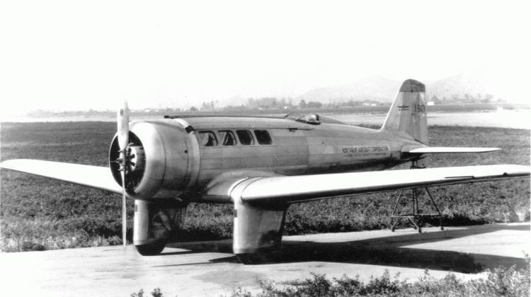
Prototyping of the 247 began in 1930 and evolved from a combination of Boeing’s previous single-engine high-performance mail plane, the Model 200 “Monomail,” and it’s twin-engine military bomber, the Model 246/Y1b-9A.

On May 6, 1930, the Boeing “Monomail” completes a successful test flight powered by a fully cowled Pratt & Whitney “Hornet” B radial engine rated at 575 hp with a maximum cruising speed of 140 mph at sea level. This new all-metal airplane has a cantilever low-wing design with retractable landing gear and three mail compartments totaling 220 cubic feet.

The United States Army Air Corps (USAAC) ordered five Boeing YB-9 bombers for assessment and tested it against other competitors’ aircraft, all competing for a new military contract. Boeing produces the YB-9 as an upgraded model based on their earlier experimental designs, the 214 and 215 models. Powered by two Pratt & Whitney 600 hp “Hornet” engines, this cantilever low-wing monoplane with retractable landing gear can carry five crew members, two machine guns and has an external explosive payload limit of 2200 pounds.

As impressive as the Boeing YB-9 is, it has its limitations, especially without any internal bomb bay. The Martin B-10 bomber is a better fit, and the Glenn L. Martin Company of Baltimore, Maryland, wins the contract.

Boeing retains the cantilever low-wing twin-engine monoplane construction of the YB-9 in designing the 247 but completely redesigns the fuselage for passenger transport. Designers add seating for ten passengers and a flight crew of three, including the pilot, a co-pilot, and a flight attendant. The wing spars of the internally braced cantilever wings became a tripping hazard where passengers had to step over them to traverse the cabin forward and aft.
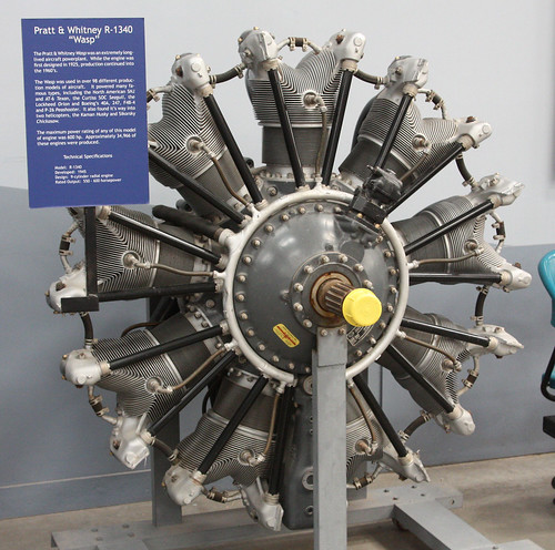
The Boeing 247 is the first airline with twin direct-drive supercharged Pratt & Whitney S1D1 “Wasp” engines rated at 550 hp at 5000 ft spinning three-bladed fixed pitch propellers and has a top speed of 180 mph. The retractable landing gear attaches under each engine mount and folds into each wing’s leading edge engine nacelles. The all-metal construction of the 247 proves durability, safety, and efficiency, which reduces the previous transcontinental flight between New York and San Francisco by seven hours, with only seven stops in less than twenty hours. United Air Lines revenue increases dramatically because of their fast and dependable schedules, passenger comfort, and aggressive advertising campaign, earning the title “Three-Mile-A-Minute-Transport.”
Boeing soon discovered that replacing the fixed-pitch propellers with variable-pitch props improved performance and added 10mph to the already impressive cruising speeds. The demand is high for the Seattle Washington Boeing Airplane Company, a division of the United Aircraft & Transport Corporation, to produce sixty aircraft on time. Boeing soon increases its workforce to thirteen hundred workers and sublets work to Stearman Aircraft in Wichita, Kansas, another division of United, to assemble the landing gears, tail wheel assembly, and various small packs for the 247.


The 247’s semi-monocoque fuselage’s main cabin has five seats on each side and seating for the flight attendant located towards the aisle’s end at the plane’s rear. The 20′ x 6′ high cabin features separate heating and air vents for each passenger, reclining seats, dome and reading lights, and convenient ashtrays. Gray-green fabric adorns the interior walls, covering insulation layers and soundproofing, making for a pleasant flight with complimenting green whipcord patterned fabric upholstered seats.

A right-side main entry door, aft of the right wing’s trailing edge, allows access to the welcoming cabin by traversing a few steps on a short rolling ladder. Once inside, one must carefully step over the interior wing spars that intersected the floor while proceeding towards the passenger cabin’s front. The wing spar is an inconvenience, but the passengers soon accept it as visual reassurance of the strength and engineering behind the new 247 design. On the left side, a small lavatory and stewardess pantry that can serve light meals during the flight sits across from the rear main entry door. A tail section cargo bay is easily accessible through a door to the left of the main entrance with a maximum capacity of 65 cu ft. A second 60 cu ft cargo area is located behind the aircraft’s nose but can only be accessed externally.

The forward-slanting windscreen quickly identifies the cockpit of the early 247’s as opposed to the later models with backward slanting windshields, but I’ll cover those other models later. All cockpits have dual controls, sliding side windows, two-way radios, state of the art navigational instruments, night-flying equipment, and a radiophone in the nose compartment’s upper area.

The stub wing is an integral part of the fuselage that firmly supports the massive landing gear, engine mounts, and nacelles. Fuel tanks also reside in the wing stub, one on each side with an additional 70-gallon reserve in the right tank. The smooth metal skin consists of anodized aluminum sheeting riveted to internal framing, resulting in a grayish exterior color often left unpainted. The all-metal tail section uses a similar cantilever design where internal bracing strengthens the horizontal stabilizer, but later models switch to fabric-covered rudders and elevators to reduce weight.

Newly designed “trim tabs” added to the ailerons’ trailing edges, elevator, and rudder allow the pilot to trim the aircraft during flight. Offset hinges installed on both the rudder and elevator provide additional aid to the pilot by reducing the amount of force needed at the control wheel to steer such a large airplane with substantial control surfaces.

This impressive aircraft measures 51′ 4″ in length and has a height of 12′ 6″ with a 74′ wingspan. It has an empty weight of 8370 pounds with a useful load of 4280 pounds, bringing the maximum gross value to 12,650 lbs. The top speed is 182 mph at 5000 ft, but a comfortable cruising speed of 161 mph at the same altitude is ideal. Climbing to 8000 ft is achieved 10 minutes after takeoff, with the initial rate of climb decreasing from 1070 ft after the first minute to 830 ft at 5000 ft. The maximum fuel capacity is 265 gallons when the tanks are filled to the caps when needed but usually run below that level resulting in 203 gallons per flight. Cruising range is about 600 miles when the pilot can manage the fuel-hungry “Wasp” engines to sip just 30 gallons each per hour.
Boeing sees room for improvements in powering the 247 and is confident that the airframe is structurally sound to handle larger engines. After discussions with Pratt & Whitney, the two reach an agreement that Boeing will modify the 247 as a test plane for their new “Twin Wasp Junior” engines currently in development and used exclusively as an executive transport for the officers of the United Aircraft & Transport Corporation. The 247-A is born.
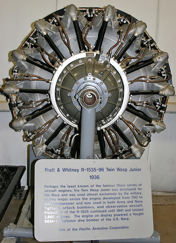
On September 14, 1933, Bernard “Benny” Whelan piloted the newly designed 247-A airliner’s first flight. “It’s a delight to fly with the increased power,” Benny remarked after landing and is impressed with the redesigned engine nacelles and broadened shrouds that now cover the more in-depth double row engines. He also enjoys seeing the new plush interior, now with spacious seating for six passengers, and still retains the rear lavatory and small kitchenette. Larger fuel tanks increase the capacity to 356 gallons extending the cruising range to about 1000 miles and reduce the number of stops on longer flights. The Pratt & Whitney SGR-1535 “Twin Wasp Junior” engine is rated at 625 hp at 2400 rpm at 7000 ft.
Engine testing continued with the installation of Pratt & Whitney’s newest development, the S1A1G engine rated at 660 hp at 2400 rpm at 7000 ft. This upgrade added 695 lbs to the total gross weight while retaining the same performance level as the previous SGR-1535 engine. Only one 247-A is produced for the sole purpose of testing and logged more than 3000 hours of flight time from 1933 to 1942 from its hanger based in Hartford, Connecticut. In 1947 the 247-A was scrapped but not before an accident-free career spanning 14 years, including two mercy flights saving both people’s lives and valuable data collected during those flight years.
The 247-A “Special” variant of the 247-A features higher torque engines, the Pratt & Whitney SA7G rated at 655 hp, increasing the gross weight to 13,650 lbs. That’s a 1000 pound increase from the original 247s gross weight of 12,650 lbs! This new 247-A “Special” also tests previous engines used in the 247-A, the 625 hp SRG-1535, and the 660 hp S1A1G with different passenger configurations leading up to the 247-D.

The 247-D is the last variation of the easily adaptable 247 in Boeing’s goal to stay competitive and easily identified by its backward sloping windshield. New supercharged Pratt & Whitney 550 hp S1H1-G “Wasp” engines fit in larger, more streamlined nacelles with close-fitting NACA cowls that reduce drag and increase speed. The 3:2 geared prop shaft spins the Hamilton-Standard “Controllable Pitch” propellers for better thrust, replacing the direct-drive fixed pitched props of the earlier 247s. The 247-D can carry ten passengers with up to 750 lbs of baggage and a flight crew of three, retaining the original configuration of the previous 247s but with an increased payload weight. Improvements to the cabin provide passenger comfort and convenience while the pilot enjoys an increase in performance and updated controls, making it easier to fly. Plus, the revised instrument panel, including an optional Sperry autopilot and Goodyear deicer boots on all leading edges. The aircraft can maintain the “Three-Miles-A-Minute” status at 3/4 throttle compared to the first 247s needing full throttle to achieve the same results due to the reduced drag and larger engines.
Pratt & Whitney S1H1-G “Wasp” engines are rated at 550 hp at 2200 rpm at 8000 ft, increasing the service ceiling from 4500 ft to 11,500 ft with one engine out under full payload compared to the earlier S1D1 engines. Gross weight remains consistent at 13,650 lbs, but the maximum speed increases to 202 mph at 8000 ft with a cruising speed at 3/4 throttle of 184 mph at the same altitude. The climb rate in the first minute is 1150 ft at sea level and can reach 11,000 ft in ten minutes with a service ceiling of 25,400 ft. Cruising range reduces to 800 miles due to the smaller fuel tanks needed to offset the extra weight of 10 passengers and their luggage, burning 66 gallons of fuel per hour at cruising speed. The redesigned all-metal tail group features additional internal strengthening under the aluminum skin and improved control surfaces. Fabric-covered rudder and elevator installed with offset hinges replace the metal cover units to reduce weight and lighten the force at the pilot’s control wheel.

On October 20, 1934, Roscoe Turner and Clyde Edward Pangborn entered a modified 247-D “Adaptable Annie” into the MacRobertson Centenary Air Race celebrating Melbourne, Australia’s 100th anniversary. This aircraft had additional fuel tanks installed into the fuselage and upgraded navigational equipment for the grueling 18,000-kilometer trip.


The flight path traversed over three continents, nineteen countries, and seven seas with five stops in Baghdad, Allahabad, Singapore, Darwin, and Charleville starting from Mildenhall, England, and finishing in Melbourne, Australia. The race has two divisions, speed, and handicap with no limitation on the aircraft, engines, or flight crew size. Turner and Pangborn finish the race in 92 hours and 55 minutes, coming in third behind a Douglas DC-2 entered by KLM piloted by the flight crew K.D. Parmentier, J.J. Moll, B. Prins, C. Van Brugge, and carrying three passengers. The DC-2 finished the race in 90 hours and 13 minutes and won the handicap division. This race showcased the strength and durability of stressed metal airplanes and that air travel over long distances is possible, making international air transport a safe alternative.

In Seattle, Washington, the Boeing factory builds thirteen new 247-Ds while the United Air Lines Overhaul Base in Cheyenne, Wyoming, converts existing 247s in their service fleet. By 1937, the 247-D finds itself becoming obsolete through fierce competition and new advances in aviation development, especially in the Douglas DC series of airliners. United decides to lease or sell most of its service fleet of 247-Ds to smaller airline companies who are more than happy to acquire them. In 1942, 27 are called into duty by the USAAF and rebranded as the C-73 for military use. By 1944, undamaged deactivated planes return to their former owners or lent to foreign countries temporarily and eventually return to the U.S.

Thanks for making it to the end and if you enjoyed reading this post, please sign up below to follow me and you will be notified by email when I upload a new post. See you soon!


/Avion%20Experimental%20No.1%20Tractor%20(NX216H)%20front%20gound%20view%20(Northrop%20photo%20via%20the%20Skytamer%20Archive).jpg)


.jpg)


You must be logged in to post a comment.